
I learnt genuine transferable principles and transferable skills such as self-motivation, problem-solving, initiative, critical analysis, responsibility, accountability, safety, accuracy, focus, precision, procedure, decision-making, prolonged concentration, self-discipline and self-management (all of which are applicable to learning the piano, studying music, and later running a business) through my father gaining permission for me in my teenage years when I was 15, 16, 17 and 18 years of age to accompany him at work in his railway signal box during the summer vacation from secondary school and later sixth-form college and also at times other holidays from secondary school and sixth-form college in preparation for a career on the railway. I also was fortunate enough to experience the workings of other signal boxes through signalmen my father knew. One such signalman was not only good at his job but excellent at providing explanations and if you had not understood the first time, a different way of explaining would be found until you did understand and then you would be tested to see if you had understood – a technique I found useful in later years when teaching.
I had plans to become either a high-speed inter-city express train driver or a signaller, and the work experience and apprenticeship with my father and his colleagues on the railway in signalling helped to considerably broaden my horizons and in addition mentally stimulated me through an environment which I found to be of beneficial and significant learning interest. It is always good to have a specialist area of knowledge and experience outside one’s current career path and my experience on the railway played a significant role in my teenage development and maturity which in turn fed into my later development as a musician and music tutor.
It was my sixth-form college teachers, however, who many years ago steered me in the direction of studying music further (particularly after I achieved highly with The Associated Board of The Royal Schools of Music Grade 8 piano practical exam and The Associated Board of The Royal Schools of Music Grade 8 theory of music exam). I then seemed to somehow find myself engaged in full-time music study for several years and later, since 1986, music teaching which is what I have done through the years to the present day.
![]()
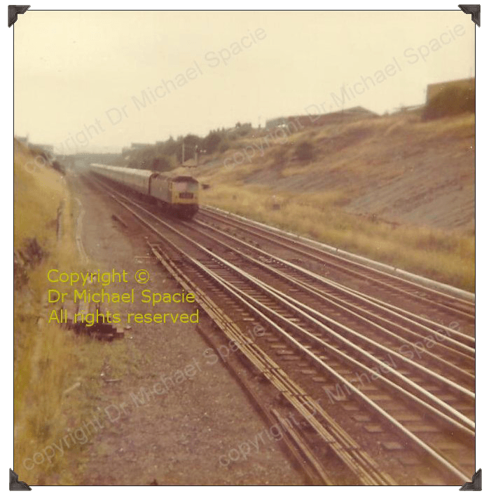
The above image shows the path set for a Class 1 Passenger Express Train on the Up Main (a South bound direction!). The train has been fully accepted, is in Signal Block Section with Block Instruments indicating status ‘Train on Line’ and Track-Circuit Diagram constantly monitoring position and progress. The Express Train can be seen just to the right of the image approaching the Signal Box at speed. Also just visible is a Multi-Aspect Colour-Light Signal Post.
Several Movements could happen concurrently, for instance, a Down Main Express (North bound) could be due and also a passenger train could be held at the branch line junction signal awaiting access to the main lines when Clearance of the Section has been obtained after the Express Train (complete with red Tail Lamp on the rear) has passed the Clearing Point of the Signal Box Section which is one quarter of a mile Ahead of the Home Signal. In order to Accept a train, the line has not only to be Clear one quarter of a mile Ahead of the Home Signal but all necessary Cross-Over Points have to be placed in their proper position and Locked for the safety of the train.
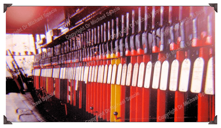
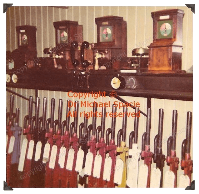
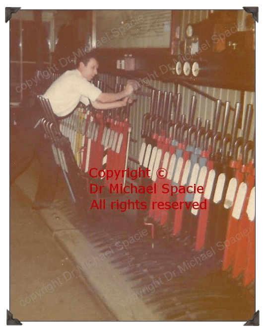
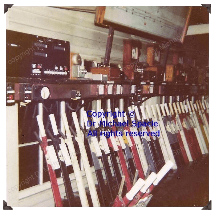
The image above displays Back-Clasp Levers responsible for Colour-Light Multi-Aspect Signals such as 2-, 3- and 4-Aspect – the latter comprising of Red, Double Amber and Green with a Double Amber Display indicating the next signal but one may be at Danger. Some Colour-Light Signals had ‘Feathers’ attached i.e. Route Indicators – a diagonal string of white lights at the top of the main signal pointing in the direction of the route to be pursued. A good modern-day example is the one visible at the South bound end of Platform 1 at Rotherham Central Station. When the ‘Feather’ is illuminated and the signal is Clear and not at Danger, the train can proceed out of the station on the Up Main, and crossing over the Down Main, leave the old Great Central Railway metals by proceeding over the Bi-Directional Holmes Cord to join the old Midland lines (from the defunct Masborough Station and the North, now used for Inter-City Cross-Country workings) to Meadowhall and Sheffield.
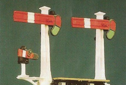
In addition, the image above also displays Levers for Upper-Quadrant Semaphore Signals; Cross-Over Points; Point-Locks; Signal Indicators and Locking-Indicators (used to check the position of Points and useful when the Points are located on a section of track the Signalman cannot see clearly or cannot see at all from the Signal Box). The block shelf houses Large Train Describer for communication with Power Signalling, Section Block Instruments of Train Describer and Block Bell with Block Telephones and Track-Circuit Diagram.
The above Signal Box uses Absolute Block whereby only one train at a time can be permitted in Section. The whole object of the Block System is to prevent more than one train being in a Block Section on the same line at the same time. Absolute Block contrasts with some other Signal Boxes where Permissive Block was operative whereby two freight (“Goods”) trains (never Passenger trains) could be following each other (adequately separated with signals) on Permissive Lines in the Block Section to avoid congestion on main lines. In some instances, Block Sections would contain both Fast and Slow Lines.
Occasionally, Passenger trains would have a “Swinger” on the rear – a single freight truck coupled to the rear coach.
![]()
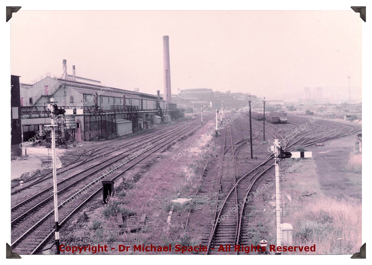
The above image shows a Down Main Express approaching the Signal Box at considerable speed. Cross-Over Points are visible as is an Upper-Quadrant Signal-Gantry.
![]()
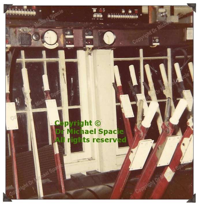
The above image shows Levers and Absolute Block Instruments consisting of Block Bell (used for receiving Bell Telegraph Codes, for example, 1 bell ring for ‘Call Attention’; 4 bell rings for a ‘Class 1 Passenger Express’; 2 bell rings for ‘Train Entering Section’; 2 pause 1 bell rings for ‘Train Out Of Section’; 3 pause 1 being a ‘Slow Passenger’ i.e. a passenger train stopping at a number of stations; 5 consecutive bell rings being the code for an Express Freight Train, although for different freight permutations, the 5 rings would include various pause combinations) and Bell Tapper used for sending Bell Codes along with Train Describer (“Pegging”) Block Instrument containing electronic Block Needle Indicator used for procedures and stages of Accepting or Refusing trains from and to other signal boxes on the line with various indications of Block Needle Positions as follows:
1) ‘Line Blocked‘ (the normal position for no train activity!). Also, if for whatever reason, proper Clearance cannot be obtained, the train must be Refused by the signalman by not moving the Block Needle of the Train Describer i.e. by leaving it showing the normal position ‘Line Blocked’. The train will then be Held.
2) ‘Line Clear‘ – a train has been offered from the previous signal box on the line. Upon Acceptance, the signals are Cleared (prepared) after the train has been offered and accepted at the next signal box. The order and sequence of Pulling Off Levers would be the Home Signal (which has nothing to do with a station!); Starter Signal (which does not mean a train has necessarily started from that signal!) and which, as a safety precaution, can only be Cleared when the Block Needle Train Describer Position is at -‘Line Clear’ (Line Clear Locking); Distant Signal – which through a Locking Device, as a safety precaution, cannot be Cleared (prepared i.e. ‘Pulled Off’) until both the Home Signal and Starter Signal have been Cleared. Distant Signals that were ‘On’ were a warning to drivers to brake as the next Home Signal could be at Danger unless the Path was Cleared on Approach.
3) ‘Train On Line‘ (train entering section of the signal box – nothing to do with the fact the train has not derailed!). The Block Instrument with Commutator (handle) is used for sending electronic Block Needle Positions and the Block Instrument without Commutator is used for receiving electronic Block Needle Positions. There are two sets of each instrument: one set for the Signal Box previous on the line, the other set for the Signal Box further on the line. The dial of the Train Describer shows three colours: Red, White and Green. The latter has particularly no function; bottom red indicates ‘Line Blocked’ (“6 O’ Clock position’); top right white indicates ‘Line Clear’; top left red indicates ‘Train On Line’.
Some Block Sections included Sidings where the train would obviously not continue on the Main Line. The Block Telephones are used for communicating Train Numbers. All Train Movements and Bell Signals Exchanged with previous and next Signal Boxes on the line are recorded in the Train Register Book.
![]()
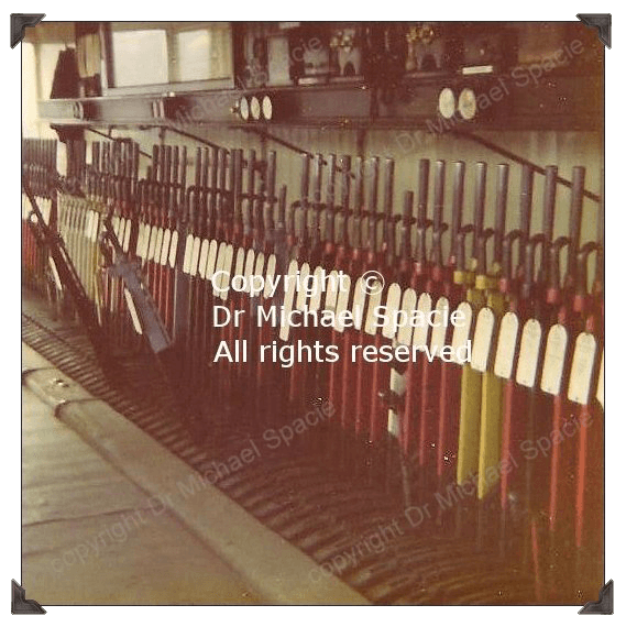
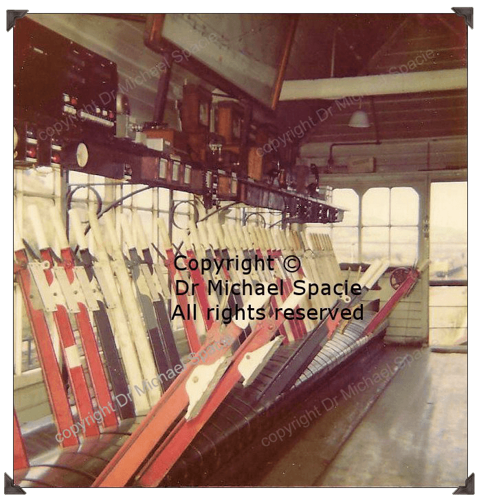
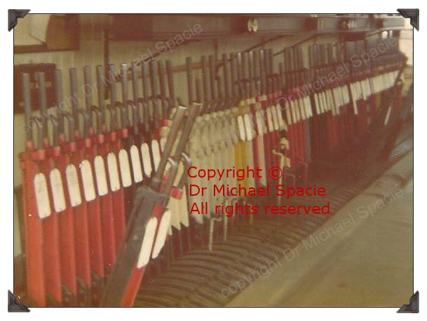
The above image shows the Lever Frame containing Front-Clasp Levers with Lever Plates (Descriptions) and are of various colours, for instance, red for Home and Starter Upper-Quadrant Semaphore Signals; yellow for Distant Upper-Quadrant Semaphore Signals; various dark colours such as black for Points and Point-Locks and white for ‘Spares’. Round disc Point-Indicators are on the block shelf above the Levers as Points have to be ‘Fitting-Up’ properly before they can be securely locked with the Locking System Lever (Lock-Bar). Once the Points are locked, a Signal can be Cleared, usually the Home Signal. As a safety precaution, if the Points are not Locked, the Signal cannot be Cleared, as the vibration and weight of the train passing over the Points at speed could move them. In other words, a Signal cannot be pulled to the Off Position unless the Points appertaining to the Movement concerned are pulled over and ‘Fitting-Up’ in the Reverse Position first. Therefore, generally, a Signal in the Off Position proves to the Signalman that the Points are set correctly with the Signal Detector Slide having been pushed fully home. Any persistent faults affecting operation would normally be reported to the Locking Linesman.
The Absolute Block System, with signal boxes as per described above, is still in use on some main lines and branch lines in the UK. An example of modern day usage of the Absolute Block System with Mechanical and Electronic Signalling using Signal Boxes such as those pictured above are the main lines in Cornwall where a mixture of Lower-Quadrant Semaphore Signals (originally introduced by the old Great Western Railway as opposed to Upper-Quadrants in most other parts of the UK including the Signal Boxes imaged above) are still used along with Multi-Aspect Colour Light Signals dealing with, amongst other Movements, Express Passenger Trains such as Virgin Cross-Country and First Great Western. Other examples on main lines are in Wales and in North Yorkshire. A modern day example nearer to home would be the main line from Sheffield to Lincoln Central. On leaving Sheffield Midland (the current station), trains pass over the Nunnery Main Line Junction controlled by Sheffield Power Signal Box and then they are passed to Mechanical Signal Boxes operated from a traditional Lever Frame and which still exist to this day at Woodhouse Junction (still controlling some traditional Semaphore Signals); Kiveton Park Station; Worksop East; Retford Thrumpton; West Burton; Gainsboro’ Trent Junction; Stow Park; Lincoln High Street (responsible for Lincoln Central Station and operating the main town level crossing). With the stated exception all have operational duties concerning Colour-Light Signals rather than traditional Semaphore. My father started his railway signalling career on this line and also operated other Great Central Signal Boxes and Midland Mainline Signal Boxes on other lines further dealing with the responsibility of passenger traffic. When I accompanied him and his colleagues it was, of course, simply known as ‘British Rail’.
However, most signalling is now controlled from large city station ‘Power Signal Boxes’ or ‘Signalling Centres’ which cover many miles of Track (now thankfully Long-Welded for passenger comfort) and embracing computer technology. Nevertheless, most of the principles are still the same and although rail passengers may not realise when travelling, the ultimate responsibility for safety lies with the Signalman as well as the Driver, as it is the Signaller who Clears the Path, Obtains Clearance and Sets the Route by securing correct Signals and ensuring Cross-Over Points are placed in their proper position together with overall control of the progress of the train which is constantly monitored by the Signaller with Track-Circuit Diagrams throughout its journey.
Finally, signalling could be physically and mentally demanding. Three shifts were worked in rotation: ‘Nights’, ‘Afternoons’ and ‘Days’. Each permutation would last for a week and each shift of eight hours’ duration with generally 12-hour shifts at two weekends out of three to allow for time off in rotation. It was not a job that offered a second chance – it had to be right the first time or the consequences for passenger safety could be catastrophic – ‘their lives in your hands’. And incidentally during busy times it was not unusual to drink tea when it had gone cold or on a good day on busy lines when dealing with Passenger and Freight Movements you might just be able to eat your ‘snap’ in one session!
![]()
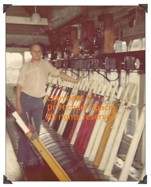
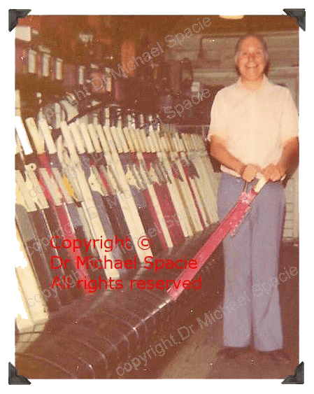
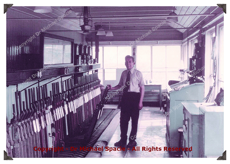
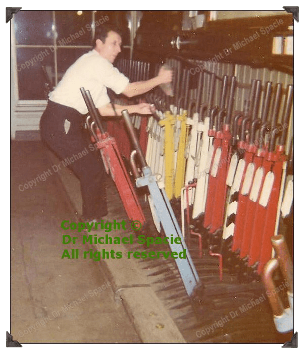
These four images show some of the signalmen at work that Michael accompanied and learnt so much from. The first image is Michael’s father.
![]()
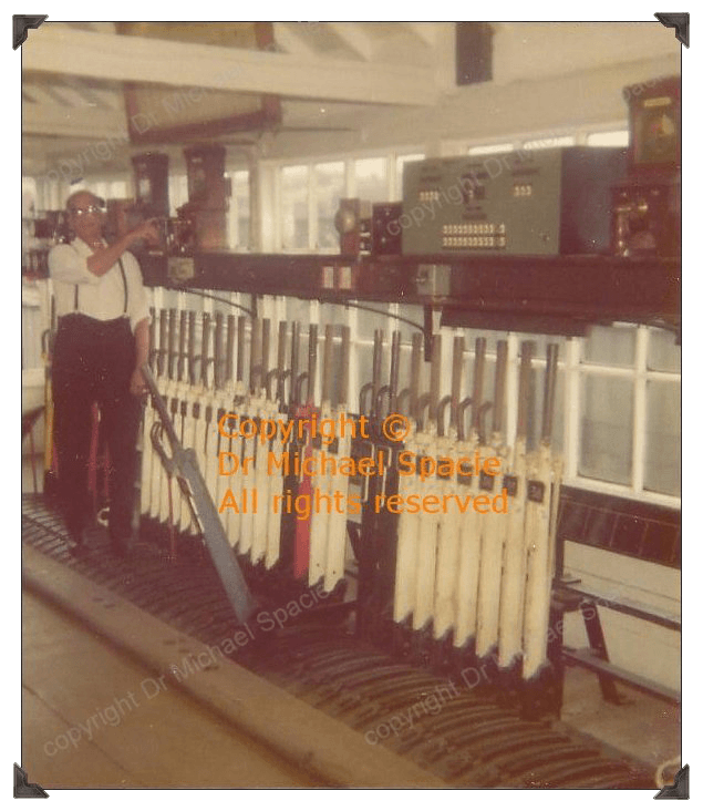
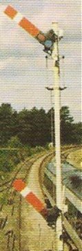
At night-time with limited visibility, signalling instruments and indicators are relied upon even more as safety has to be paramount – trains do not reduce speed simply because it is dark!
![]()
General Comment of Explanation
All railway signalling is to a large extent bespoke, designed for specific locations. Safety aspects such as Interlocking, whereby the Points and Signals are linked mechanically and/or electrically in order to prevent potentially Conflicting Moves being set up were a major development in signalling. Likewise, Electric Signals and applications of electricity to signalling such as Track Circuits further aided safe working. The essential concept of a signalman controlling all Points and Signals in a defined section of railway track known as a Block Section is still paramount today. The Block Sections can vary in length, and Access in some parts of the country is still controlled by signalmen communicating with each other using Bell Codes on Block Instruments for the Class of Train as well as other Bell Codes for emergencies such as a carriage door open whilst the train is in motion or a carriage becoming uncoupled; there was even a Bell Code for the then royal train! Communication was also by Block Telephones for Train Numbers etc. Semaphore Signalling was always the norm since the inception of the railways, but so-called modernisation in the 1970s and particularly the 1980s saw a mixture of Semaphore and Multi-Aspect Colour-Light Signalling. Today, it is mostly the latter aided with computerisation although a number of areas in the UK still use Semaphore, for example in some parts of Wales and Cornwall, but by no means limited to these areas. It is good to see that the art of railway mechanical signalling is still used.
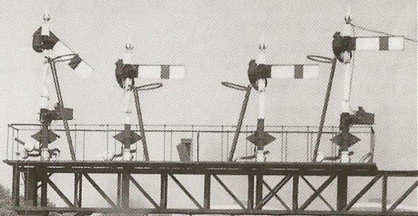
Semaphore Signals take two forms:-
Stop Signals: the function of these is to Stop trains when their arms are ‘On’ or at Danger i.e. in the horizontal position (arms showing the ‘Proceed’ position are known as being ‘Off’).
Distant Signals: these give advance notice to the driver of the state of the next Stop Signal. When ‘Off’, a Distant Signal tells the driver that all the relevant Stop Signals under the control of the Signal Box being approached are also Off.
Stop Signal Arms are rectangular and painted red with a white stripe on the front face (and white with a black stripe on the reverse). Distant Signal Arms are notched at the ‘free’ end, and painted yellow with a black chevron on the front face (and white with a black chevron on the reverse side).
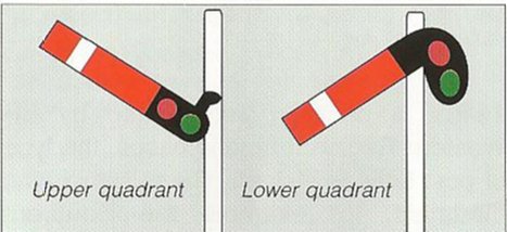
Semaphore Arms show clear to Proceed in two ways: ‘Upper-Quadrant’ whereby the Arm is raised through about 45 degrees from the horizontal, and ‘Lower-Quadrant’ known as ‘Drop-Semaphore’ (largely used on the Great Western Railway as previously mentioned) whereby the Arm is lowered by the same amount from the horizontal. As hitherto stated, these are still used to this day, good examples being evident along with Block Section Mechanical Signal Boxes at some stations in Cornwall, signalling CrossCountry and First Great Western HSTs amongst other traffic. The Lower-Quadrant was not favoured by other railway companies due to a Lower-Quadrant Signal possibly indicating the wrong position i.e. ‘Off’ should a signal wire break – as the Signal Arm would simply drop; whereas a signal wire fracture in an Upper-Quadrant would mean it could not be Pulled Off and would remain at Danger. Incidentally, more than once I have seen signalmen be thrown flat on their back if they are Pulling Off a signal up to a quarter of a mile away or more on a heavy Frame and Lever and the Signal Wire has snapped in spite of using a cloth to grip the Lever. In those days it was part and parcel of your duties and you simply got up and got on with the job without a word to anyone except a grouse to your colleague in the next Signal Box and a call to the S. & T. (Signal & Telegraph) fitters to come and sort it. You could alter the Signal Wire Tension (sometimes necessary in Summer due to expansion) by means of mechanical wheels (to be seen to the left of the door frame at lever height on the first image on this page) but generally signalmen didn’t like using them as they were not fitters. One signalman told me he once knew of a colleague who took the end of his finger off operating one. Probably with hind sight, if the signalman couldn’t get the Signal ‘Off’, rather than operate the tension wheel, he would have been better Hand-Signalling with Flags (Green/Red) and instructing the driver verbally (the latter using a telephone integrated in a Signal Post) to pass the signal at Danger or to stop the train outside the Signal Box and speak to the driver in person. There would have probably been a few grumbles and chosen words from the crew as Express Trains in particular, although at times inevitable for safety and Block Section Clearance, didn’t like to be slowed or stopped because of essential time-keeping. However, there could be a number of Operational reasons as to why a train could be delayed. Generally, the further a train was delayed, the more it would lose its (timetabled) Path, often then throughout its journey having to await Block Section Clearance between other Movements or Access to a Station Platform, adding and compounding to further delays. However, the majority of Express Movements did run to time on their designated Paths.
For Signal Construction, there were various types of signal post and these varied greatly. The chief material was wood, although many were lattice posts. Tubular steel posts were widespread also. The bespoke nature of Semaphore Signalling means that many different types can be found, for example, attached to retaining walls or Multiple Arms on the same Post on bracketed or Stand-Alone Signal Posts having one or more Arms.
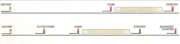
The Home Signal is the first Stop Signal under the control of the Signal Box at the end of the Section of track through which the train has just travelled. Other Stop Signals called Starting Signals allow trains to leave the Section. If required, additional Stop Signals are provided, such as an Advanced Starter or an Outer Home, as well as Subsidiary Signals such as a Calling On Arm for Light Engine Movements (i.e. locos without carriages or freight) and Ground Signals for Shunting. As there are normally two sets of tracks i.e. an Up and Down Main to allow trains to travel in opposite directions (excepting Bi-Directional working), the signal sequence and order would be: Advanced Starter Signal, Starter Signal, Home Signal (or Inner Home Signal), Outer Home Signal and Distant Signal; these would be the opposite way round for each track, as viewed from the Signal Box. However, not all signals and points could be seen by the signalman from the Signal Box even during daylight hours and thus instruments had to be relied upon for the current status of such signals and also points.
Junction Signals are arranged whereby the Diverging Route has the shorter post from that of the Principal Route.
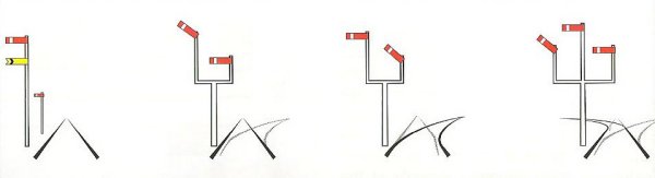
The above Signal Diagram (extreme right illustration) has two Outer Stop Arms on equal-length posts called ‘Dolls’. The Subsidiary Arms allow Access to Junction Branches etc. These are on shorter Dolls than that of the Principal Route (the middle Doll). The Diverging Arm is placed to the left or right of the Main Arm as required (see above diagram), and in the case of two or more Diverging Routes, additional Arms are provided. Where the provision of individual posts is impractical for space and/or visibility reasons, Signal Gantries were erected across multiple tracks as Signals are only as good as their visibility to drivers.
Signal sighting is a practised art even today with Multi-Aspect Colour Light Signals, and every effort is made to ensure they are as easy to ‘read’ as possible in spite of signals now being read automatically by various safety systems such as AWS (Automatic Warning System) where the driver has to acknowledge manually an automatic ‘reading’. Factors that are still taken into consideration when sighting signals are such things as changeable weather conditions; night-time visibility; possibility of confusion with other signals and so on.
Occasionally to make signals more visible, very tall signals were erected to make them stand out against the sky and above buildings and obstructions. Often, these lofty installations had Co-acting Arms lower down the Signal Post repeating the position of the Upper Arm to drivers close to the post. In some cases white boards were attached to the post to make the Arm stand out against a busy background. Night-time visibility was aided with a lamp at the end of the Signal Arm that would shine through a green-coloured disc for the ‘Off’ position of an Upper-Quadrant when Pulled Off and red for ‘On’ i.e. the Danger position. Safety has, and is still, the focal point of railway signalling and will always remain so.
The first image at the top of this page shows an approaching Fast Passenger hauled by a ‘Deltic’ Locomotive. These consisted of 22 in the fleet, were complex machines and the originals were painted in green livery but later, blue was the norm. They were made by English Electric in the 1960s to largely replace the Gresley A4s. The Deltics served in main stream service until about 1982 when they began gradually to be withdrawn from service throughout the following years, although some are still operational. The second image on this page is of a ‘Brush’ Class 47 hauling a Fast Passenger and had a similar life-span to the Deltics.
The Deltics were replaced with the modern HSTs (High Speed Trains) that we see today i.e. a ‘complete’ Set with a Power Unit at the front and rear. These were first marketed as ‘Inter-City 125’ and some of the old BR (British Rail) Rolling Stock are still used, for example, by First Great Western and some East Midlands Trains. They were so-called ‘Inter-City 125’ because they easily maintained line speeds of 125mph on some sections of track throughout the UK. Excepting Eurostar, this is the average and maximum speed issued for a number of UK line speeds with the exception of the old Great North Eastern Railway (London Kings Cross to Edinburgh) where there are sections of line speed enabling modern East Coast Electric Expresses to travel at 140mph, authorization for which is indicated with Double Flashing Green lights of a Multi-Aspect Signal Post. The increased speed acceptable on the GN is due to the superb Victorian engineering and where there are many miles of straight track without tight curves and the curves that do exist can mostly be negotiated at speed. This contrasts with the old Great Central Railway of whose lines pass through the new Rotherham Central Station; that old company being affectionately known as the ‘String and Basket’ due to its bumps of ‘shake, rattle and roll’ – something that can be sampled to this day on the Sheffield to Lincoln Central line hitherto mentioned. On the whole, things are much improved nowadays, although the 1980s constructed Single Track Bi-Directional Holmes Chord curve situated after departing South Bound for Meadowhall from Rotherham Central can only be described as ‘tight’. The Midland lines running through the old Masborough Station in Rotherham were built for more speed and as hitherto mentioned earlier on this page and now carry a number of HST workings by CrossCountry trains amongst other traffic.
The ‘new’ Rotherham Central Railway Station was opened on Monday 11th May 1987. The station was partly built on the site of the old Rotherham Central Station which was closed to passengers in 1966. Since that time the former stretch of Great Central Railway was only used by freight trains with mechanical signal boxes controlling sections from south to north (Sheffield to Doncaster direction): ‘Tinsley East’/’Ickles’/(Rotherham Central Railway Station)/’Rotherham Main’/’Rotherham Road’/’Greasbrough Road’/’Aldwarke’ etc., but as previously mentioned, a then half-mile stretch of track, the ‘Holmes Chord’, brought in 1987 the Sheffield/Doncaster/Hull or Cleethorpes route and Nottingham/Chesterfield/Sheffield/Wakefield/Leeds route right into the centre of Rotherham. In 1987, more stations were connected by through trains from Rotherham Central than nowadays, although at the time of opening in 1987 the Sheffield/York trains still called at the now closed Rotherham Masborough Station on the old Midland route. Rotherham Central Station also underwent a further rebuild, modernisation and remodelling mainly in the year 2011 which, of course, is the station we have at present.
In summary, I was fortunate enough to have been in a position of great learning during my mid to late teenage years through the railway signalmen that greatly helped my intelligence to develop (much more so than my comprehensive secondary school who did not really cater for anyone who had any spark and certainly not any specific music abilities – but that’s another story). All this was in the not-too-distant past when a working class workforce existed and when, as a young person, you knew something of what it was like to work in a manual work-place, which often, was your only chance of learning anything. There was certainly nothing humiliating or demeaning for a young person to learn about a life craft, trade and skill with its notions of endeavour and duty. There was no academic environment here, nor was it necessary, nor any ‘entitlement’ or ‘equality’ – just simply hard work which undoubtedly helped to develop you as a whole person. Through being ‘apprenticed’ from a young age, one was actually taught to do something economically and productively useful – a tool for life – that not only helped (unexpectedly as it was) to professionally develop in music but has proven to be beneficial time after time again – both inside and outside my music teaching business.
On a final note, due to increased legislation, health and safety, ‘red tape’ and so forth, there is no way, at least in the majority of cases and instances, a son could accompany his father at work nowadays – that era has gone and sadly with it the enriching benefits of learning, experience, maturity and wisdom of the real world that it brought.
Dr Michael Spacie
![]()
With the exception of the purely illustrative images under the ‘General Comment of Explanation’ section, the sixteen original photographs (and resultant digital images) appearing on this page were taken by and are owned by Dr Michael Spacie.
All text on this page is written and owned by Dr Michael Spacie and is the result of Michael’s learning on the railway. The image descriptions are written to somewhat enhance understanding and are not intended to be an exhaustive account of railway signalling which would be irrelevant in this context. The descriptive and analytical information given merely “scratches the surface” of a detailed and complex subject.
All contents of this page
Copyright © 2026
Dr Michael Spacie
All rights reserved
![]()
![]()